Author Archives: admin7489

The software

Available from : https://www.qsl.net/dl4yhf/spectra1.html

Spectrum Analyzer with Waterfall Display and real-time audio processing

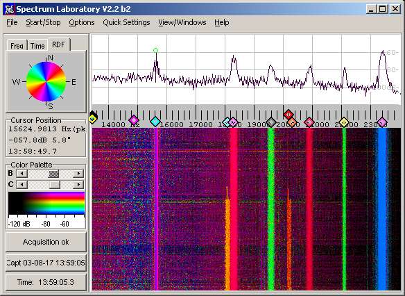
This program started as a simple FFT program running under DOS a long time ago, but it is now a specialized audio analyzer, filter, frequency converter, hum filter, data logger etc (see history). You can download it from this site. Or look into the manual (in HTML format), even though the manual included in the archive will be more up-to-date. Furthermore, the same manual has occasionally been converted into a single PDF (SpecLab_Manual.pdf), but any attempt to create a common index and table of contents for this PDF, using OpenOffice (with proper page numbers instead of the hyperlinks) has failed miserably – see note in the preface of the PDF document.
If you are looking for a short description in German language, look here. The revision history is here. How to use SpecLab with SDR-IQ is described here; how to use SpecLab with PERSEUS (without an annoying virtual audio cable) is here, and how to use SpecLab with software-defined radios supporting ExtIO (instead of a soundcard), like FiFi-SDR, RTL-SDR, FunCube, SDRplay RSP, etc etc, is described here.

VLF equipments

ESH 2 TEST RECEIVER from Rhode and Schwarz, for use as Field-strength Meter 9 kHz to 29,9999 MHz / -30 to +137dBuV
SPM-60 receiver from Wandel and Goltermann, Selective Level Meter 200 Hz to 18.6 MHz
USB soundcard 192 kHz 24 bits
Spectrum analyser MT8820A
The model 2230 A is a Programmable Frequency and Level Generator.
Frequency range: 50 Hz to 1 MHz
Resolution: 1 Hz resolution
The output frequency can be controlled according to four operating modes: digital setting by six lever / indicator switches, remote programming in parallel BCD code or through the IEEE bus, analog setting by two verniers with graduated scale, frequency sweep by external signal. 
Four output signals are simultaneously available:
Main output with push-button selectable impedance: 75 ohms coaxial, 150 ohms balanced, 600 ohms balanced or low-impedance balanced (key 0 ohm)
Auxiliary output with Z < 1 ohms impedance
Square-wave output with 5 V or 10 V amplitude
Tracking output delivering a signal with 4 MHz offset with respect to the dialed or programmed frequency
his device outputs low-jitter reference clock frequency-locked to GPS signal.
Long term stability of output signal is defined by high accuracy of GPS Caesium references and approaches 1×10-12.
Short term signal quality is defined by internal TCXO clock source providing high-quality, low phase noise clock signal with sub-picosecond RMS jitter.
Digital PLL allows main output reference frequency to have almost any value between 400Hz and 810MHz.
Output signal is a square wave at 3.3V CMOS levels with 50 Ohms characteristic impedance. Output drive level can be adjusted.

Description of antenna

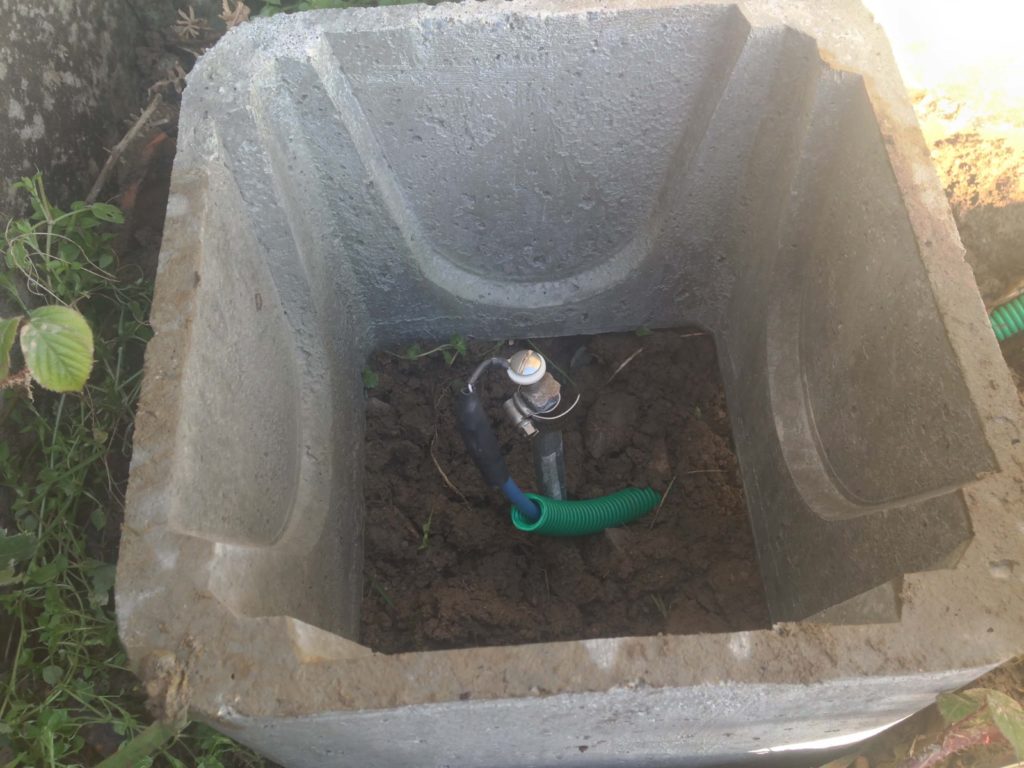
I use ten galvanized steel spikes. Two meters long on a field of 50 x 15m.

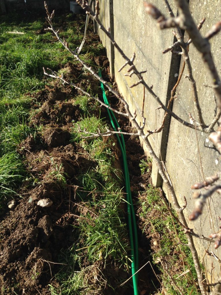
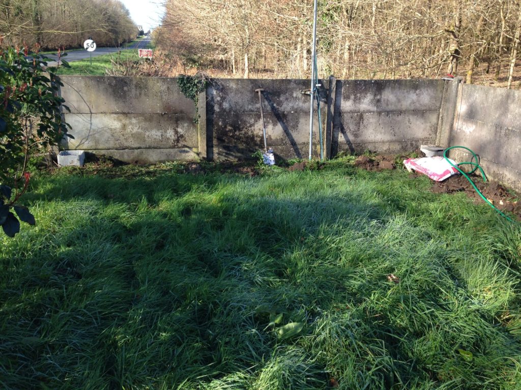
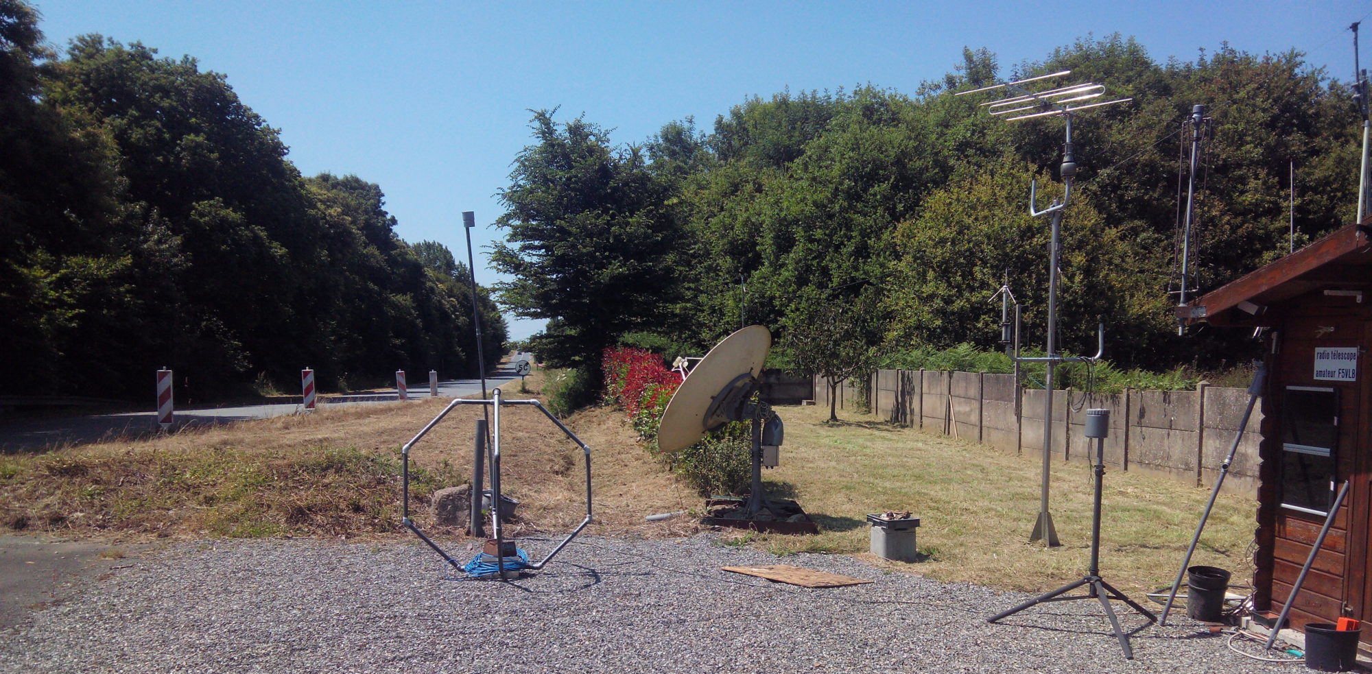
I have placed the antennas so that I can select the ones that best align with the direction I want to explore. The land is oriented east-west.

My position is 48.56N -3.32W altitude 202m. The region is called Brittany, the village Louargat (the fight of the moon in local language).

The spike is driven as far as possible into the ground, protected by a concrete block with inspection cover. An RJ45 cable, shielded with 4 pairs of wires, is connected to the head of the spike. I then protected the cable / spike junction with self-adhesive aluminum tape. The cable is protected by an electrical sheath.
The cable (one per spike) is buried.
The two probes at the end of garden. The road indicates west.
The RJ45 cable – between marshaling box and the shack
Cable between EPA and the marshaling box. The RJ45 cable – each pair is with aluminum foil, there is a copper braid shielding, a pvc jacket. Using this cable assure me the signal is not picked by the cable.